

In my previous article, “Another FAA Outage: What We Know,” I discussed the November 13 nationwide FAA ground stop and some of the confusing terminology being used to describe the failure.
Terms such as TDM, IP, copper, fiber, analog, digital, old routers and new routers were sometimes being used almost interchangeably. They are not interchangeable.
Since then, additional information from the FAA, Department of Transportation, L3Harris and others has helped clarify what happened and, perhaps more importantly, the network in which it happened.
We still do not have a complete technical root-cause analysis, but the picture is becoming considerably more interesting.
Two Locations Are Now Being Investigated
The FAA now says its initial investigation has identified two potential locations associated with the excessive network traffic: a radio communications site near El Dorado, Arkansas, and a radar site near Amarillo, Texas.
L3Harris, the FAA’s current telecommunications network service provider, had been performing work at the El Dorado location, including deployment of a new router. When the network instability developed, L3Harris blocked the two locations and the network stabilized.
The FAA has also said that a broadcasting function was disabled on all of the new routers as a precaution while the investigation continues. That adds considerably more detail to the original description that routers were simply being “overloaded with data.”
According to the Department of Transportation, the network experienced more than 1,000 connection attempts every four to five seconds, ultimately affecting communications and radar information at 17 of the FAA’s 22 Air Route Traffic Control Centers. Would love to see a packet capture of that!!!
We still do not know exactly what those connection attempts were, what protocol generated them, or precisely what the broadcasting function did. Those remain important unanswered questions.
L3Harris Is More Than an Equipment Vendor
As I researched the incident further, one point became very clear. L3Harris did not simply sell the FAA a router.
L3Harris is the prime managed-services contractor for the FAA Telecommunications Infrastructure, or FTI, the nationwide telecommunications system connecting thousands of FAA facilities.
The relationship dates back more than two decades to Harris Corporation, which later merged with L3 Technologies to become L3Harris Technologies.
L3Harris says it designed, implemented, operates and maintains the nationwide private FTI wide-area network. The company says FTI connects more than 4,400 FAA locations, delivers more than 29,000 telecommunications services, and supports more than 50,000 users. Its Network Operations Control Center monitors and manages more than 100,000 communications devices 24 hours a day, 365 days a year.
Under the managed-service arrangement, L3Harris says it owns the equipment used to provide FTI services and leases telecommunications connectivity from multiple carriers. So L3Harris should not be thought of as the equivalent of Verizon, AT&T or another nationwide physical carrier.
It is better understood as the prime network integrator, managed-service provider and network operator, combining carrier services, site equipment, optical transport, routers, multiplexers, network management and operational support into an end-to-end service for the FAA.
That makes its role in the November 13 incident considerably more significant.
FTI Is Not Simply an Old TDM Network
Another thing that became clearer during this research is the nature of FTI itself. FTI provides both legacy TDM services and modern IP services.
L3Harris explicitly describes a private, secure Operational IP backbone that carries FAA IP traffic, along with an optical backbone using redundant Points of Presence and diverse DWDM optical paths. Critical services at major FAA facilities also use redundant optical Metro Ring designs.
At the same time, many FAA systems have historically presented legacy TDM interfaces. FAA documentation describing the TDM-to-IP migration makes this distinction very clearly. The administrative Mission Support network was already fully IP-based, while the NAS operational environment supported a combination of TDM and IP interfaces. In 2015, more than 90 percent of approximately 23,000 FTI services were still TDM-based because of the interfaces required by the FAA systems using them.
That is an important distinction.
The FAA can have a legacy TDM service interface at one location while other portions of the end-to-end communications path use optical transport, Ethernet and IP.
That is why describing the November 13 event simply as a failure of an “old TDM network” remains misleading.
Reconstructing the FTI Network
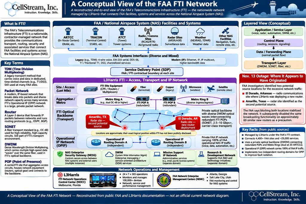
Using publicly available FAA and L3Harris documentation, I created the accompanying diagram titled: A Conceptual View of the FAA FTI Network
It is important to understand what this diagram is — and what it is not.
It is not an official FAA network diagram.
It does not show actual current router addressing, routing-protocol adjacencies, interfaces, security policies, carrier assignments or exact physical paths.
It is instead a derived conceptual architecture, assembled from information the FAA and L3Harris have publicly disclosed over many years combined with my 30+ years experience in both TDM and modern Data Networking.
The top of the diagram represents the systems FTI must connect: Air Route Traffic Control Centers, TRACONs, airport towers, remote radio sites, radar installations, weather systems and other National Airspace System facilities.
Those FAA systems can present very different telecommunications interfaces. Some are legacy interfaces such as analog voice, serial connections, T1, DS3 or other channelized TDM services. Others use Ethernet, IP and IP multicast.
Those interfaces reach what the FAA calls the Service Delivery Point, or SDP — essentially the contractual boundary between the FAA system and the FTI telecommunications service. FAA documentation defines the SDP specifically as the point where the telecommunications contractor interfaces with the government.
On the FTI side of that boundary are site equipment, routers, multiplexers and telecommunications access services.
The physical access may involve:
- fiber,
- legacy copper,
- microwave,
- satellite,
- or other carrier services.
L3Harris confirms that FTI uses multiple telecommunications carriers and a variety of access technologies to reach both major FAA facilities and small remote locations. Those services ultimately feed into the larger FTI transport infrastructure.
Public L3Harris material describes redundant FTI Points of Presence, diverse optical paths, DWDM transport and dual Metro Ring architectures at critical facilities.
Above that transport infrastructure sits the FAA’s private Operational IP network, providing routed connectivity for operational NAS applications.
Other logical environments include the Mission Support network, enterprise security gateways and systems such as System Wide Information Management, or SWIM. FAA architecture documents explicitly identify Operational IP, Mission Support IP and enterprise security as separate functional elements of FTI.
Finally, the infrastructure is monitored and managed through L3Harris network operations personnel and FAA operational-support organizations.
L3Harris currently advertises positions at its Melbourne, Florida Network Operations Control Center specifically supporting both IP and TDM FTI operations. The technical requirements listed in those jobs include Ethernet, IP, T1/T3, SONET, TDM and other technologies — another useful illustration of just how hybrid this environment really is.
Where Do the Suspect Routers Fit?
The two red locations shown in my conceptual network diagram represent the approximate publicly reported areas associated with the November 13 investigation. They should not be interpreted as exact FAA facility coordinates or exact positions within the FTI backbone.
- The El Dorado location is described by the FAA as a radio communications site where L3Harris was deploying a new router.
- The Amarillo location is described as a radar site and the second potential source of the excessive data.
Conceptually, these appear to be site/access locations feeding into the larger FTI infrastructure, rather than the national backbone routers themselves.
That distinction makes the incident particularly interesting. A remote-site router should normally have a relatively limited failure domain. Yet whatever happened on November 13 propagated far enough through the FTI environment to produce instability affecting 17 of 22 en-route air traffic control centers.
That leads directly back to what I believe is now the most important networking question: Why was a problem originating at one or two remote FAA sites capable of acquiring such a large national blast radius?
An Interesting Historical Parallel
This is also not the first time a router-related problem has propagated through FTI.
In November 2009, a router replacement activated a dormant configuration problem that resulted in erroneous routing information propagating into the FTI IP backbone. Traffic was redirected, network resources became overloaded and a substantial portion of FTI IP connectivity was disrupted. The FAA subsequently convened a review panel, which documented the event in considerable technical detail.
There is no basis at this point for saying the November 2026 failure was caused by the same mechanism. It may be completely different.
But there is an interesting architectural similarity:
routine router work → abnormal network behavior → propagation → widespread service impact.
That makes the eventual November 2026 technical root-cause report particularly important.
What We Still Need to Learn
We now have a much better idea of the environment in which the failure occurred. What we still do not know is the protocol-level explanation.
- What were the “connection attempts”?
- What exactly did the router broadcasting function broadcast?
- Why were those messages able to propagate beyond the local site?
- Which routers or network resources became overloaded?
- Was the constrained resource bandwidth, CPU, memory, connection state, control-plane capacity or something else?
- Were both redundant routing or transport paths exposed to the same condition?
- What fault-containment mechanisms existed?
- And why did they not prevent a remote problem from affecting such a large portion of the National Airspace System?
Until those questions are answered, we still have a description of the incident rather than a complete technical explanation.
But we know considerably more today than we did immediately after the ground stop.
And perhaps the most important lesson remains the same: This is not adequately explained by saying “old TDM,” “old copper,” “old routers” or “too much data.”
The FAA telecommunications environment is a complex hybrid network containing legacy TDM services, modern packet networking, optical transport, carrier access, routing infrastructure and thousands of geographically dispersed endpoints. Understanding what actually failed requires separating those components rather than lumping them together.
I will continue following the investigation and will update this analysis as the FAA and L3Harris provide additional technical details.
Sources Used for This Analysis
- FAA — Nationwide Ground Stop: Questions and Answers. The FAA’s latest description of the El Dorado and Amarillo locations, the new router deployment, blocking of the two locations and disabling of the broadcasting function on new routers. FAA Nationwide Ground Stop Q&A
- U.S. Department of Transportation — November 14, 2026 briefing. Source for the L3Harris maintenance activity, copper-to-fiber migration, 1,000 connection attempts every four to five seconds, impact on 17 ARTCCs, and FAA Administrator Bryan Bedford’s comments regarding router replacement. DOT November 14 briefing
- U.S. Department of Transportation — November 13, 2026 briefing. Documents the initial characterization of the outage and the early discussion of TDM, IP, routers and network instability. DOT November 13 briefing
- L3Harris — FAA Telecommunications Infrastructure Program Profile. Primary source for the current FTI managed-service architecture, 4,400+ FAA sites, 29,000+ services, 100,000+ monitored devices, Operational IP backbone, DWDM transport, redundant POPs and Metro Rings. L3Harris FTI Program Profile
- L3Harris — FAA Telecommunications Infrastructure. Describes the current copper-to-fiber modernization, multiple-carrier model, fiber, satellite and wireless access technologies and the role of L3Harris in maintaining FTI during the transition. L3Harris FTI overview
- FAA — FTI-2 Program Objectives. Public architectural documentation describing Operational IP, Mission Support IP, enterprise security and the scope of the FTI service environment. FAA FTI-2 Program Objectives
- FAA — TDM-to-IP Migration. Explains the FAA’s historical dependence on TDM services, the coexistence of TDM and IP within the NAS operational network, and the migration pressures created by carrier retirement of legacy services. FAA TDM-to-IP Migration paper
- FAA — Maintenance of FAA Telecommunications Infrastructure Services. Useful historical documentation defining the Service Delivery Point and the division of responsibilities between the FAA and the FTI contractor. FAA FTI maintenance document
- FAA — FTI Review Panel Report on the November 19, 2009 Outage. Detailed technical report documenting an earlier FTI router/routing failure and the structure of the IP and optical backbone at that time. FAA 2009 FTI outage report
- Professional Aviation Safety Specialists — Nationwide Ground Stop statement. States that the November 13 issue was isolated to two contractor-owned and maintained routers being updated during the day. PASS statement
- Reuters — November 14–15 coverage. Independent reporting on the nationwide impact, the Arkansas and Texas router investigation, continued airline disruption and the ongoing root-cause investigation.
Stay tuned as we learn more.
If you would like to help support the continued development of independent networking, broadband, Wi-Fi, VoIP, and packet analysis content, please consider joining our Patreon community where you will gain access to exclusive technical resources, downloadable labs and PCAPs, bonus course content, troubleshooting guides, and additional member-only material. Comments and technical discussion are always welcomed at our Patreon community or on our Discord server. You can also support our work by simply buying us a coffee — every contribution helps us continue creating practical, real-world network science education for professionals and enthusiasts alike.