
A broadband technician working with fiber optics must understand both the theory and the hands-on operational realities of fiber networks. The following areas represent the core knowledge required to install, maintain, and troubleshoot fiber effectively in access and distribution networks.
1. Fiber Fundamentals
Technicians must understand how fiber carries data as light, not electricity. Fiber-optic cable carries information using light energy, not electrical current, because its physical construction and operating principles are fundamentally different from copper conductors. Optical fiber is made of glass or plastic, which are dielectrics (electrical insulators).
- No free electrons are available to flow as current
- Electrical voltage applied to fiber does nothing
- This is why fiber is immune to lightning, ground loops, and EMI
Electricity may exist at the electronics on each end, but never inside the fiber strand itself. Light is generated at the transmitting end. This is a LED or laser diode converts electrical signals into light pulses. Light represents binary data (on/off, different intensities, or phases). Common wavelengths include 850 nm, 1310 nm, and 1550 nm. Once converted, the electrical signal is gone—only photons enter the fiber. At the receiving end a photodiode converts incoming light back into an electrical signal. The network device processes the signal as Ethernet, IP, voice, or video. The conversion back to electricity only happens after the light exits the fiber.
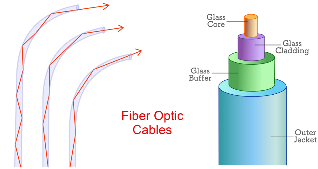
Fiber has two key layers:
- Core – the central glass where light travels
- Cladding – surrounding glass with a slightly lower refractive index
This difference causes total internal reflection, trapping light in the core. Light entering the fiber at the proper angle reflects off the core-to-cladding boundary. It continues bouncing down the fiber with minimal loss. It does not leak out unless bent or damaged. This optical behavior has no electrical equivalent—it is purely physics of light.
2. Fiber Types and Use Cases
Knowing the correct fiber for the application is essential. There are two primary types of fiber-optic cable used in broadband networks: single-mode fiber and multi-mode fiber, each optimized for different distances, costs, and applications.
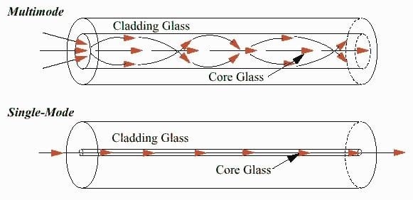
Single-mode fiber (SMF) uses a very small core (approximately 9 microns) that allows only one path—or mode—of light to travel down the fiber. Because the light travels in a nearly straight path with minimal reflection, signal distortion and attenuation are very low, making single-mode fiber ideal for long-distance applications such as access networks, feeder routes, and backbone infrastructure. SMF typically operates at 1310 nm and 1550 nm wavelengths and supports distances ranging from tens to hundreds of kilometers with the proper optics. While the fiber itself is relatively inexpensive, the associated lasers, splicing precision, and test requirements are more demanding, which increases overall system cost.
- Long distances (access, feeder, backbone)
- Common wavelengths: 1310 nm, 1490 nm, 1550 nm
- Yellow jacket
- Core size: 9/125 µm
- Used for ISP, FTTH, Starlink backhaul
Multi-mode fiber (MMF) has a much larger core (commonly 50 or 62.5 microns), allowing multiple light paths to propagate simultaneously. These multiple modes cause greater dispersion, which limits the effective transmission distance compared to single-mode fiber. MMF is commonly used for short-distance applications such as inside buildings, equipment rooms, and data centers, typically operating at 850 nm using LED or VCSEL light sources. Multi-mode systems are generally less expensive and easier to deploy but are not suitable for long-haul or outside-plant broadband networks due to distance and bandwidth limitations.
- Short distances (inside buildings, data centers)
- Core sizes (50/125 µm, 62.5/125 µm)
- Orange/Aqua jacket
Here are some important fiber optical transmission terms:
- TX (Transmit) – Sends light
- RX (Receive) – Receives light
- Wavelength – Color of light (850nm, 1310nm, 1550nm)
- Bidirectional (BiDi) – Single fiber using different wavelengths for TX/RX
3. Structure, Connectors, Adapters, and Polarity
The following is a list of different Fiber types or Fiber Cable Structure
- Simplex Fiber – One fiber strand
- Duplex Fiber – Two fiber strands (TX & RX)
- Armored Fiber – Has metal protection
- Figure-8 Cable – Fiber + steel messenger (pole mounted)
- ADSS Cable – All-dielectric self-supporting (no metal)
Connector issues are among the most common fiber faults. Fiber connectors are the mechanical termination points that allow optical fibers to be connected to equipment, patch panels, or other fibers while maintaining precise alignment of the fiber cores. Common connector types include SC, LC, ST, and MPO/MTP, each designed for specific density, handling, and application requirements.
- SC Connector
- Square
- Push-pull
- Common in FTTH & media converters
- LC Connector
- Small form factor
- Used in SFP modules
- ST Connector
- Twist-lock
- Older networks
- FC Connector
- Screw-on
- Industrial use

The connector ferrule holds the fiber end in exact position, and the end-face polish—most commonly UPC (Ultra Physical Contact) or APC (Angled Physical Contact)—directly affects optical performance. UPC connectors have a flat end face and are typically blue, while APC connectors have an 8-degree angled end face and are usually green. Mixing UPC and APC connectors causes high reflections and significant signal loss, making proper identification and matching critical for reliable broadband service.
Fiber adapters, also called couplers, are passive alignment devices that join two connectors together. Their sole function is to maintain precise core-to-core alignment while minimizing insertion loss and back reflection. Adapters are designed to match both the connector type and polish, such as SC-to-SC UPC or LC-to-LC APC, and are commonly installed in patch panels, wall plates, and fiber distribution frames. A mismatched adapter—whether by connector style, polish type, or cleanliness—can introduce excessive loss or reflections that degrade link performance. As with connectors, adapter cleanliness is essential, since contamination inside the sleeve can affect both fibers simultaneously.
- UPC (Ultra Physical Contact)
- Blue
- Flat end
- −50 dB loss
- APC (Angled Physical Contact)
- Green
- 8° angle
- −60 dB loss
- Used in FTTH / GPON
- Never mix UPC and APC

Fiber polarity refers to the transmit-to-receive orientation of fibers within a duplex or multi-fiber link, ensuring that the transmitter on one end connects to the receiver on the other. In simple duplex links, polarity is maintained by reversing one end of the fiber pair so that Tx aligns with Rx. In higher-density systems using MPO/MTP connectors, polarity becomes more complex and is managed through standardized methods (commonly referred to as Type A, Type B, and Type C polarity schemes). Incorrect polarity results in a physically intact fiber link that does not pass traffic, making polarity verification a necessary step during installation and troubleshooting in modern broadband and data-center environments.
4. Cleanliness Is Critical
Contamination is the #1 cause of fiber problems. An “Inspect before you connect” approach is mandatory. Dust, oil, or residue can cause major optical loss (even fingerprints). This requires proper use of inspection scopes, lint-free wipes, and cleaning tools.
Cleanliness is critical in broadband fiber optics because fiber operates on microscopic alignment and precision, where even invisible contaminants can severely degrade signal performance. A single dust particle, oil residue, or skin oil on a connector end face can partially block or scatter the light traveling through the fiber core, resulting in increased attenuation and back reflection. Because the core of single-mode fiber is only about 9 microns wide—roughly the size of a red blood cell—contamination that cannot be seen with the naked eye can obstruct a significant portion of the light path, leading to intermittent errors, reduced optical margins, or complete link failure.
Dirty connectors also cause cascading damage throughout the network. When a contaminated connector is mated, debris can be transferred into adapters or onto previously clean connectors, spreading the problem across patch panels and equipment ports. In severe cases, contaminants can be burned onto the end face by high-power laser light, permanently damaging connectors and requiring costly replacement. For this reason, industry best practice mandates “inspect before you connect,” using fiber inspection scopes and proper cleaning tools to ensure end faces are free of debris before every connection is made.
From an operational perspective, poor fiber cleanliness leads to difficult-to-diagnose service issues. Links may pass initial power tests yet fail under load, or exhibit intermittent performance that mimics electronics or protocol problems. By contrast, consistent inspection and cleaning dramatically reduce troubleshooting time, prevent unnecessary truck rolls, and protect sensitive optical transceivers. In broadband environments where reliability and uptime are critical, cleanliness is not optional—it is a fundamental requirement for maintaining optical integrity and service quality.
5. Splicing and Termination
Technicians must understand both mechanical and fusion splicing because each method serves distinct operational, economic, and environmental roles in broadband fiber networks. Mechanical splicing provides a fast, low-cost way to restore service or complete temporary or low-count connections, particularly in field repairs or emergency situations. It requires minimal equipment and setup, making it practical for technicians working in access networks, customer drops, or remote locations. However, mechanical splices typically introduce higher insertion loss and reflection, and their long-term reliability is more sensitive to temperature changes, vibration, and physical stress. Understanding these limitations allows technicians to choose mechanical splicing appropriately without compromising network performance.
Fusion splicing, by contrast, is the gold standard for permanent fiber connections, especially in backbone, feeder, and high-capacity access networks. By precisely aligning and permanently fusing two fiber ends with an electric arc, fusion splicing produces extremely low loss and minimal reflection, resulting in superior optical performance and long-term stability. Fusion splices require specialized equipment, controlled preparation, and skilled technique, but they provide predictable results that support tight optical budgets and high-bandwidth services. Technicians who understand fusion splicing principles can correctly interpret splice loss measurements, protect splices within trays and enclosures, and recognize when a poor splice—not electronics or configuration—is the root cause of service degradation.
A technician who understands and can perform both splicing methods can make sound engineering decisions in real-world conditions. This knowledge enables proper tradeoffs between speed, cost, and performance, prevents inappropriate use of temporary solutions in permanent infrastructure, and improves troubleshooting accuracy. In modern broadband networks, where optical margins are often tight and customer expectations are high, splicing competency directly impacts network reliability, service quality, and operational efficiency.
6. Optical Power and Loss Budgets
A technician must know whether a link should work before turning it up. Optical power and loss budgets define whether a fiber-optic link can operate reliably before it is placed into service. The optical power budget is the difference between the transmitter’s output power and the receiver’s minimum sensitivity, expressed in decibels (dB). This value represents the total amount of signal loss the link can tolerate while still functioning correctly. Loss accumulates from fiber attenuation over distance, connector losses, splices, splitters, and any passive components in the path. By calculating the expected total loss and comparing it to the available power budget, technicians can determine if a link should work, identify how much margin exists, and avoid deploying circuits that are destined to fail or perform unreliably.
Understanding loss budgets is critical for installation, troubleshooting, and future-proofing broadband networks. If measured loss exceeds the calculated budget, technicians know the issue is physical—such as dirty connectors, excessive bends, poor splices, or damaged fiber—rather than a configuration or protocol problem. Conversely, having sufficient margin allows for normal aging of components, temperature variation, and future repairs without service impact. In access and PON environments, where split ratios significantly increase loss, accurate budget management becomes even more important. Mastery of optical power and loss budgets enables technicians to validate designs, interpret test results confidently, and maintain long-term network reliability.
- Optical loss budget calculation: Total Link Loss (dB) = Fiber Loss + Connector Loss + Splice Loss + Component Loss + Engineering Margin
- Typical loss values:
- Fiber: ~0.35 dB/km (1310 nm)
- Connector: ~0.2–0.5 dB
- Splice: ~0.05–0.1 dB
- Engineering margin: Typical margin: 2–3 dB
7. Test Equipment and Interpretation
Fiber troubleshooting requires specialized tools.
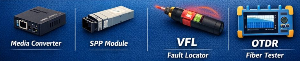
- Media Converter – Converts fiber ↔ Ethernet (e.g., HTB-GS-03-20KM)
- SFP Module – Pluggable fiber transceiver for routers/switches
- VFL (Visual Fault Locator) – Red laser for checking breaks
- Optical Power Meter (OPM) – verifies received signal strength
- Light Source / OLTS – validates end-to-end loss
- OTDR – locates breaks, bends, splices, and reflections. One must have the ability to interpret OTDR traces correctly (events vs artifacts)
8. Bend Radius and Physical Handling
Fiber is durable—but not indestructible. Bend radius and physical handling are critical considerations in fiber-optic networks because fiber carries light through a precisely engineered glass structure that is highly sensitive to mechanical stress. Every fiber cable has a specified minimum bend radius, defined separately for conditions under tension (during pulling) and after installation. Exceeding this limit causes light to escape the core, increasing attenuation and reflections. Tight bends—often hidden behind patch panels, inside enclosures, or at customer premises—can degrade performance without visibly damaging the cable, leading to intermittent or wavelength-specific failures that are difficult to troubleshoot.
Improper physical handling also introduces long-term reliability risks. Excessive pulling tension can stretch the fiber, micro-crack the glass, or damage internal strength members, while sharp bends or compression can create microbends and macrobends that permanently increase loss. Poor slack management, inadequate strain relief, and improper routing in splice trays or cabinets further compound these issues over time. By respecting bend radius specifications, using proper pulling techniques, and securing fiber correctly within enclosures, technicians protect optical integrity, preserve loss budgets, and prevent latent failures that can surface long after installation is complete.
9. Safety Awareness
Fiber introduces hazards technicians must respect. Safety awareness is essential in broadband fiber optic networks because fiber introduces hazards that are not immediately visible but can cause serious injury if ignored. Active fiber circuits may carry invisible infrared laser light that can damage eyesight if viewed directly, even though no light is visible to the human eye. For this reason, technicians must never look into the end of a fiber or connector and should always assume a fiber is live unless it has been properly tested and verified as dark. Safe work practices include using power meters or visual fault locators designed for fiber, rather than relying on sight.
Fiber work also presents physical safety risks unique to glass-based media. Cleaving and splicing produce microscopic glass shards that can easily penetrate skin or eyes and are difficult to detect or remove. Proper personal protective equipment, controlled work surfaces, and strict disposal procedures—such as using dedicated fiber scrap containers and adhesive mats—are mandatory. Additionally, technicians must be aware of environmental hazards such as working in confined spaces, aerial installations, or near energized electrical infrastructure. Consistent adherence to fiber safety protocols protects technicians, preserves network integrity, and ensures compliance with industry safety standards.
- Invisible laser light can damage eyesight
- Glass shards from cleaving and splicing
- Proper disposal of fiber scraps and PPE usage
10. Integration with Broadband Services
Fiber is part of a larger access ecosystem. Fiber optic networks integrate with broadband services by serving as the physical transport layer that carries high-capacity data between service providers and end users, while higher-layer technologies deliver Internet, voice, and video services over that optical foundation. In access networks, fiber is commonly deployed using Passive Optical Network (PON) or Active Ethernet architectures, where optical signals are distributed from a central office or headend to customer locations. At the network edge, optical signals terminate at devices such as optical line terminals (OLTs) or Ethernet switches on the provider side and optical network terminals (ONTs) at the customer premises. These devices convert light into electrical Ethernet frames, enabling IP-based services to function transparently over the fiber infrastructure.
From an operational standpoint, fiber is service-agnostic, meaning it does not inherently understand Internet, Wi-Fi, voice, or video—it simply transports optical signals with defined power and quality characteristics. Technicians must therefore be able to distinguish between true optical-layer problems (loss, reflections, breaks, or contamination) and issues that originate in Ethernet, IP routing, authentication, or Wi-Fi within the customer environment. Proper integration requires verifying optical performance first, then correlating those results with higher-layer service behavior. This layered understanding allows broadband technicians to isolate faults accurately, avoid unnecessary equipment replacement, and ensure reliable delivery of modern broadband services over fiber.
Summary
We hope this post helps those broadband technicians with a reference of fiber optic terms. operations, and definitions.
Fiber carries light—not electricity—because it is an insulating optical waveguide. Electrical signals are converted to photons at the transmitter, guided through the glass core by total internal reflection, and converted back to electrical form at the receiver. This separation is what makes fiber immune to EMI, capable of extreme bandwidth, and ideal for modern broadband networks.
Fiber-optic delivery of broadband services is preferred because it provides significantly higher performance, reliability, and long-term scalability than copper-based or wireless alternatives. Fiber carries data as light, allowing it to support extremely high bandwidth with very low signal loss over long distances. Unlike copper, fiber is not affected by electromagnetic interference, electrical noise, lightning, or ground potential differences, which results in more stable connections and consistent service quality. This makes fiber particularly well suited for modern broadband demands such as gigabit- and multi-gigabit Internet, cloud applications, streaming video, and latency-sensitive services.
Another key advantage of fiber is its future-proof nature. The capacity of a fiber link is largely determined by the electronics on each end rather than the fiber itself, meaning service providers can dramatically increase speeds by upgrading optics without replacing the physical cable. In contrast, copper and coaxial systems have hard physical limits that require extensive rebuilds to deliver higher performance. Fiber also supports longer reach, fewer active components in the field, and lower maintenance requirements, which reduces operational costs and improves network reliability over time. For these reasons, fiber optic infrastructure is widely regarded as the most robust and sustainable foundation for delivering broadband services now and well into the future.
A competent broadband technician must treat fiber optics as a precision optical system, not just a cable. Success depends on cleanliness, correct handling, proper testing, and the ability to correlate optical measurements with real-world service performance.
If you would like to help support the continued development of independent networking, broadband, Wi-Fi, VoIP, and packet analysis content, please consider joining our Patreon community where you will gain access to exclusive technical resources, downloadable labs and PCAPs, bonus course content, troubleshooting guides, and additional member-only material. Comments and technical discussion are always welcomed at our Patreon community or on our Discord server. You can also support our work by simply buying us a coffee — every contribution helps us continue creating practical, real-world network science education for professionals and enthusiasts alike.